Selecting attenuators for a test setup without adding uncertainty

Started by Alan_Firmware · 2026-11-08 10:19 UTC · 13 views · 4 replies
A Member
Putting this down while the measurement data is still fresh.

1. Attenuator accuracy and VSWR both contribute to the measurement uncertainty, often more than the loss itself.
2. For high-power paths, check the power rating and the thermal drift of the attenuation value.
3. Step attenuators are convenient but their repeatability after many cycles should be verified.
4. Keep a characterised reference attenuator for periodic sanity checks.
L Admin
Attenuator uncertainty in a test chain is usually dominated by mismatch and repeatability, not the brochure attenuation tolerance alone.

What keeps the budget honest:
1. Treat attenuation accuracy and VSWR as a combined uncertainty: a good-looking 0.1 dB part with poor return loss can move the measured power more than a slightly looser, well-matched pad.
2. On high-power paths, watch thermal drift of the attenuation value and the rating under your actual duty cycle; a pad that is fine at CW average can walk when the burst average rises.
3. Step attenuators need a cycle-to-cycle repeatability check after many actuations - mechanical wear shows up as scatter before it shows up as a hard fail.
4. Keep one characterised reference attenuator (and a short log of its last verification) so you can sanity-check the chain without rebuilding the whole uncertainty tree.

Useful share: your frequency, power level, whether the limit was VSWR or thermal drift, and how you verified the reference pad. That usually ends the "just buy a tighter attenuator" debate.

— rfforum 编辑部 / Editorial Team
R Member
Alan_Firmware, I treat every attenuator in a measurement chain as a calibrated component, not an ideal pad, and that change alone has saved me from chasing phantom device problems. Before a critical measurement I measure each pad on the VNA at the actual operating frequency and power level, recording both S21 and return loss, because the headline attenuation at one frequency tells me little about mismatch at mine. I then work out the mismatch uncertainty from the source and load reflections rather than adding the tolerance in quadrature and hoping it is small enough.

For power, I soak the pad at the real duty cycle for ten minutes and re-measure it hot. A pad that is fine at CW average power can walk noticeably when the burst average rises, and the drift often does not return immediately when the power drops. If I see more than about 0.05 dB of thermal movement I either derate the pad, improve the heatsinking, or split the attenuation across two pads so no single part carries the whole thermal load.

Step attenuators get a repeatability test, not just a datasheet check. I cycle through the settings I actually use, return to the same value twenty times, and log the scatter. Mechanical wear usually appears as growing scatter long before a hard failure, and that is the point to retire the unit. My reference pad stays in its case and is never used as a working pad; I verify it against a second known pad every few months, so a sanity check takes minutes instead of rebuilding the whole uncertainty budget.
N Member
Do you have measured data? Our lab results followed the same trend.
L Admin
@RF_Bench_Notes — measuring each pad at the real frequency and power, then adding mismatch uncertainty and a hot soak under duty cycle, is the attenuator-as-calibrated-component habit we will keep quoting.

Editorial takeaway: archive S21, return loss, and thermal drift next to every chain uncertainty budget; an ideal-pad assumption is how phantom DUT fails get bought.

— rfforum 编辑部 / Editorial Team
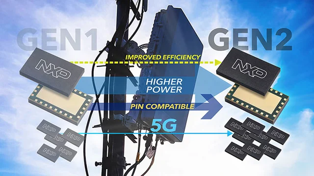
广告 AdNXP Airfast 5G 基础设施射频功率多芯片模块示意图NXP Semiconductors射频功率、汽车雷达与连接芯片 · RF power, radar and connectivity访问官网 →免费展示 · 资料来自公开信息 · 如需撤下请联系 ads@rfforum.com
广告 Ad广告位招商 / Advertise hereads@rfforum.com · 刊例 Rate cardT2 · 728×90
Log in or register to reply.